
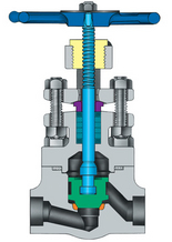
Pars Regulator API 602 small, forged valves
- Features and benefits
- A compact but extremely sturdy design for high pressure-temperature service.
- Solid CoCr Cobalt chrome alloy wedge (optional) ensures low friction and long service life.
- For Class 1500 valves and for steam service, seats are seal-welded to the body.
- Packing rings are pre-compressed to 4000 psi to provide a high integrity seal.
- For welded bonnet valves, the bonnet is threaded in and torqued to an engineered torque value and the body bonnet joint is strength-welded, offering double protection against leakage. (Body/bonnet threads and strength-weld).
- A fully guided wedge reduces wear on seating surfaces.
- Repairable 2-piece stem drive.
- Parallel slide gate valves are also available.
- Optional design available with double packing, leak-off connection, live-loading, and a packing blowout for easy removal of old packing.
ASME Classes 150 – 4500
Standard connections
Threaded, socket weld, flanged
What is Gate valve?
Gate valves (also known as knife valves or slide valves) are linear motion valves in which a flat closure element slides into the flow stream to provide shut-off. They are one of the most used valves.
| Advantages | Disadvantages |
| Available in large sizes | Low pressure limitations |
| Can be used with slurries and viscous liquids | Slow open and close time |
| Used as a shut off valve | Erosion of the seat and disk can occur |
| Easy to maintain and disassemble | Poor throttling characteristics |
| Inexpensive | Difficult to repair |
| Inherently fire-safe (when used with a metal sheet) | Should not be used in sanitary applications |
| Bidirectional |
Gate valves and knife valves are advantageous in applications involving slurries, as their “gates” can cut right through the slurry. They are also used in applications that involve viscous liquids such as heavy oils, light grease, varnish, molasses, honey, cream, and other non-flammable viscous liquids. They are available in large sizes to better handle thick flow. However, gate valves do have low-pressure limitations, and are not optimal in applications that require cleanliness or sanitary conditions. They are excellent for use anywhere a shutoff valve is needed. When needed, they can also be used where throttling capabilities are desired, although this is not recommended as erosion of the seat and disc occurs due to the vibrations of the disk in throttling applications.
Gate valves and knife valves are designed to minimize pressure drops across the valve in the fully opened position and stop the flow of fluid completely. The direction of fluid flow does not change, and the diameter through which the process fluid passes is equal to that of the pipe. Hence, they tend to have minimal pressure drop when opened fully.
Valve Function
Gate valves are primarily designed for on-off services. They are best used in systems which require infrequent use of the valve. The valves are designed for full-area flow to minimize the pressure drop and allow the passage of a pipe-cleaning pig. Since most of the flow change occurs near the shutoff, the high fluid velocity causes disk and seat wear and eventual leakage if the valve is used to regulate flow.
Applications
Gate valves are used in many industrial applications including the oil and gas industry, pharmaceuticals, manufacturing, automotive, and marine.
Non-rising stem gate valves are extremely popular on ships, in underground applications, or where vertical space is limited because they don’t take up extra space. Gate valves can be used in demanding environments such as hot temperatures and high-pressure environments. They are often seen in power plants, water treatments, mining, and offshore applications.
Types
Gate valves are usually divided into two types: parallel and wedge-shaped.
The parallel gate valve uses a flat disc gate between two parallel seats, upstream and downstream. Shut-off is obtained by the free-floating seat or disk gate that allows the upstream pressure to seal the seat and disk against any unwanted seat leakage. Some parallel gate valves are designed to allow the seat to be spring energized by an elastomer that applies constant pressure to the disk gate seating surface. In the double-disk parallel-seat type, the valve is closed by lowering the disks from the valve neck to a height equal to that of the valve seats. Once so positioned, an inclined plane mounted between the two disks converts downward stem force into axial force and presses the parallel disks firmly against the valve seats sealing the two openings. These types of valve design can accommodate asymmetric or angularly misaligned valve seats. Parallel gate valves are used in low pressure drops and low pressures, and tight shutoff is not an important prerequisite.
Knife valves are a specific type of parallel gate valve. They have a sharp edge on the bottom of the gate to shear entrained solids or separate slurries.
The through-conduit gate valves have a rectangular closure element. The closure has a circular opening equal to the full-area flow passageway of the gate valve. As the element is lowered the opening is exposed to the flow. Raising the element shuts off the flow. In this design the seating surface of the gate is always in contact with the gate.
Wedge-shaped gate valves use two inclined seats and a slightly mismatched inclined gate, allowing for tight shut-off.
Disk flexibility is inherent to the split wedge design. This flexibility allows the split wedge to seal more easily, and it reduces stickiness between the sealing surfaces in cases where the valve seats are angularly misaligned. The mismatched angle is also designed with some free movement to allow the seating surfaces to match with each other as the actuator forces them closed. It is also best used for handling non-condescending gases and liquids at normal temperatures, particularly corrosive liquids. Pressure-energized elastomer inserts can be installed on a solid gate to provide a tight seal. This type of disk should be installed vertically.
Solid wedges are the most common because of their simplicity and strength. They can be installed in any position, are suitable for all fluids, and are practical for turbulent flow.
Flexible wedge gate valves are commonly used in steam systems. The disk is one piece with a cut around the perimeter to improve the ability to match errors or change the angle between the seats. Varied sizes, shapes, and depths are available. For example, a shallow, narrow cut gives little flexibility but retains strength. A deeper, wider cut leaves little material at the center and weakens the disk but increases flexibility. Flexible wedges prevent binding the gate within the valve when the valve is in the closed position. The design allows the gate to flex as the valve seat is compressed by heat from the steam in the system. The disadvantage is that water tends to collect in the body neck.
Flow
As a gate valve is opened, the flow path is enlarged in a highly nonlinear manner with respect to the percent opening. The flow rate does not change evenly with the stem travel and the disk in a partially opened gate valve will vibrate from the fluid flow. Since this vibration can cause the seat and disk to wear and cause leakage, gate valves should only be used in the fully open or fully closed position. Little friction loss occurs when the valve is in the fully open position.
Method of Control
The closure element of a gate valve is a replaceable disk. To open the valve, the disk is completely removed from the stream and offers no resistance. Therefore, there is little pressure drop across the open gate valve. A fully closed gate valve provides good sealing due to the 360° disk-to-seal ring contact surface. Proper mating of a disk to the seal ring ensures there is little or no leakage across the disk when the gate valve is closed.
Media
Gate valves can be used for liquid and gas services. They are especially designed for slurries with entrained solids, granules, and powders. They can also be used for cryogenic and vacuum services.
Gate Valve Components
There are three main parts of a gate valve: body, bonnet, and trim.
Body
The body of a gate valve holds all the operational parts of the valve. It is connected to the system with one of the mounting options below. The mounting option should be selected based on the current system mounting features and the type and size of the media.
| Threaded | The valve has internal or external threads for inlet or outlet connection(s). |
| Compression fitting | A sealed pipe connection without soldering or threading. As the nut on one fitting is tightened, it compresses a washer around the second pipe, forming a watertight closure. |
| Bolt Flange | The valve has a bolt flange(s) for inlet or outlet connection. |
| Clamp Flange | The valve has a clamp flange(s) for inlet or outlet connection. |
| Union | The valve has a union connection for inlet or outlet connection(s). |
| Tube fitting | The valve has a connection for directly joining tubing at the inlet and/or outlet connections. |
| Butt weld | The valve has a butt weld sized connection for inlet or outlet connection. |
| Socket weld/solder | The valve has a socket weld connection for inlet or outlet connection. |
| Metal face seal | The valve has a metal gasket sandwiched between two fitting parts. The gasket forms a face seal on each side of the fitting. |
Bonnet
The bonnet of a gate valve contains the moving parts and is attached to the valve body. The bonnet can be removed from the body to allow for maintenance and replacing parts.
Trim
The trim of a gate valve contains the functioning pieces of the valve: the stem, the gate, the disc or wedge, and the seat rings.
Stem – The stem of a gate valve is either a rising stem or a non-rising stem. The stem is responsible for the proper positioning of the disk. Non rising stems will always have a pointer-type indicator mounted onto the upper end of the stem to indicate valve position. This configuration protects the threads from carrying dirt into the packing because the stem threads are held within the boundary of the valve packing. Rising stems rise out of the flow path when the valve is opened. They can either have a stem that rises through the handwheel or have a stem that is threaded to the bonnet.
Seat – The seat of a gate valve is either integral with the valve body or in a seat ring type of configuration. The seat ring construction is either threaded on to the body or pressed into position and the seal welded to the valve body. Pressed and welded is recommended for higher temperature applications. Press-in or threaded-in seats permit variation in the seat material verses the material of the body of the valve.
It is important to consider the size of the valve and system when selecting a gate valve. Gate valves are linear motion valves and therefore are taller than other manual valves. This is especially true if the valve uses a rising stem. Most of the time gate valves should be installed horizontally (perpendicular to the ground) with the manual actuator in the top position. This allows for easy access for maintenance and replacing parts. Smaller gate valves can be installed in vertical lines, but gravity tends to pull the valve out of alignment.
Material of Valve Construction
Gate valves are used in a wide variety of applications and may meet an assortment of media. When selecting a gate valve, the material used to construct the valve is a critical decision to prevent premature valve failure or system delays. To select the proper valve material there are several important criteria to be considered:
- The composition of the media in contact with all wetted (exposed) parts
- Service temperatures
- Operating pressures
- Effectiveness of coating on materials
- Material availability and cost
- Compatibility of materials with injected media.
- How long the valve will be exposed to the media
There are organizations dedicated to developing and maintaining standards for valves and materials in particular environments. Gate valves are available in many varied materials. Valves can be specified by the National Association for Corrosion Engineers (NACE) and the American Petroleum Institute (API) for their ability to handle strong and corrosive media.
Actuator
Valve actuators open and close the valve in response to a signal or manual manipulation. Most gate valves have manual actuators, such as a handwheel, because they are commonly used in applications where the valve does not need to be opened or closed often or quickly. Since gate valves are not used in throttling applications, the actuator is responsible for fully opening and fully closing the valve.