
Introduction to Needle Valve
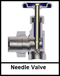
Needle Valves, sometimes referred also as Plunger Valves, are regulating valves and enable engineers to finely control and regulate fluid flow and pressure. Needle valves are like the globe valve in design with the biggest difference is the sharp needle shaped disk. Needle valves have a small port and a threaded needle-shaped plunger. This arrangement permits a very gradual increase or decrease in the size of the opening allowing precise regulation of flow, although it is only capable of low flow rates.
Needle valves can operate manually or automatically. Automated needle valves are connected to a hydraulic motor or an air actuator that automatically opens and closes the valve. The motor or actuator will adjust the plunger’s position according to timers or external performance data gathered when monitoring the machinery. Both manually operated and automated needle valves provide precise control of the flow rate.
One design feature of most needle valves dictates that a considerable number of turns are required to make even a small amount of space open. This enables gradual, accurate and precise control over the amount of liquid/gas that can pass through the valve. Additionally, this can prevent damage to gauges which could be affected by sudden bursts of liquid/gas and allows for better control and regulation in general.
Needle Valve Working Principle
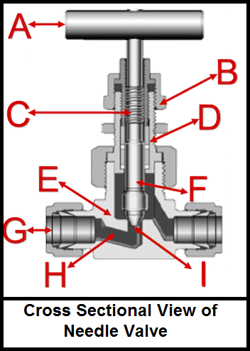
Needle valves open and close an orifice like valve opening with a tapered needle shaped disc that raises and lowers with the spin of a hand-wheel or with the help of any automatic control mechanism. Figure on the right shows a needle valve cross sectional view, design, and components. The hand-wheel (A) is connected to the plunger, also called stem (F). When one turns the handle, the plunger moves up or down based on the threads (C). The locking nut (B) prevents the plunger from fully unscrewing. As the plunger moves down, the tapered pointed end (I) meets the valve seat to fully seal the valve opening (H). Often, the valve seat is also tapered. The valve’s needle-like plunger fits into the seat. Because of this unique design, a needle valve can precisely and accurately control how much fluid passes through the valve. When the hand-wheel is turned in one direction, the plunger is lifted to open the valve and allow fluid to pass through. When the hand-wheel is turned in the other direction, the plunger moves closer to the seat to decrease the flow rate or close the valve. There are various options and sizes available to connect it to a pipe or hose through the port connection (G) on the inlet and outlet. The bonnet (D) is connected to the valve housing (E), which can be made from different materials like brass or stainless steel.
Uses of Needle Valve
- Needle valves are frequently used as metering valves. Metering valves are used for extremely fine flow control.
- Needle valves are used to control flow and protect delicate gauges from damage caused by sudden pressure surges of liquids and gases.
- Needle valves are used in low-pressure hydraulic systems, chemical processing, and other gas and liquid services.
- Needle valves are used in flow-metering applications, especially when a constant, calibrated, low flow rate must be maintained for some time.
- Since flow rates are low and many turns of the valve stem are required to completely open or close, needle valves are not used for simple shutoff applications.
- Small, simple needle valves are often used as bleed valves in water-heating applications.
- One of the most used locations for needle valves is to monitor gas flow, like propane, in a system.
- Needle valves are also sometimes used in vacuum systems, to release a controlled yet steady supply of gas without a great amount of pressure.
Needle Valve Selection Requirements
When selecting a needle valve, four main characteristics and/or application requirements need to be considered:
- Material of Construction
- Fluid Pressure
- Port or Orifice Size
- Fluid Temperature.
Material of Construction
The needle valve’s housing material is specified according to the application it is being used for. The most common valve housing materials are brass and stainless steel due to their range of chemical resistance, however, there are also other materials available for special applications.
Fluid Pressure
Robust needle valves can handle pressure of up to 4,000 to 5,000 psi (275 up to 413 bar) at 100°F (38°C). When higher pressures are required, like for high pressure hydraulic applications, high performance valves are available that can handle up to 10000 psi (689 bar) pressure at 100°F (38°C). Special designs are also available when you need a vacuum needle valve to handle the low pressure.
Port & Orifice Size
Needle valves are available in a wide range of port and orifice sizes. The connection ports can also be male or female ends. The most used needle valves range from 2 to 12 mm or 1/8” to 2”. Ensuring the correct port size and orifice size will ensure efficient flow and system operation with less chances of wear and/or leakage.
Fluid Temperature
Needle valves are suitable for high or low temperature applications. For extreme temperatures one needs to specify the valve housing and packing/sealing material appropriately to ensure the needle valve can withstand the requirements. The two most common sealing materials are PTFE (Teflon) for a temperature range of -65°F to 450°F (-54° C to 232°C) and PEEK (Polyether Ether Ketone) for increased temperature resistance up to 600°F (315 °C).